SIMPLE ROCKET ANALYSIS
Internal Chemistry
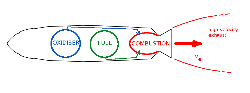
A rocket motor is typically designed to convert internal chemical energy via compustion to kinetic energy of an exhaust gas. The momentum change due to expulsion of the exhaust gas will produce the trust required to propel a vehicle forward.
There are two main types of rocket motor: liquid fueled and solid fueled.
In the first case a liquid fuel is fed into a combustion chamber along with an oxider to produce a combustion reaction that produces high temperature and pressure in order to drive the exhaust products out through an exit nozzle.
Alternately a monopropellant fuel may be passed through a catalyst plate to produce the required chemical reaction. In this class of motor separate fuel and oxidiser tanks are required along with turbine or similar pumps to generate required fuel flow rates. In many cases the fuel will need to be pressurised or stored in cyrogenic tanks as it is not liquid at room temperature. This adds significant weight to the system. For low gravity and extreme environment considerations these tanks and fuel lines may require additional anti-sloshing, pressurisation, heating/cooling or heat regeneration components. The big advantage of liquid fueled engines is the ability to control thrust by being able to vary fuel flow rates and to be shut down and then restarted as required.
In the case of solid fuel rockets, fuel and oxidiser are pre-mixed into a solid material matrix. Once this material is ignited, combustion continues through the fuel/combustion chamber until all material is exhausted. The main advantage here is the lightness of required supporting structures and lack of a complex fuel storage, pumping system. The disadvantage is a greatly reduced amount of control of thrust variation for the motor.
There are a large number of possible chemicals that can be used as fuel or oxidiser for rocket motors. For engineering purposes the critical parameter is the amount of thrust produced compared to the amount of fuel being consumed by the motor. The standard measure of performance is called Specific Impulse ($I_{sp}$). It can be defined as follows,
$$I_{sp}={\text"Specific Impulse"}={\text"Total Impulse"}/{\text"Amount of Fuel Used"}$$
Total Impulse ($I$) is the force ($F$) produced for a given period of time.
$$\text"Total Impulse"=I=FΔt=∫F.dt$$
Therefore
$$I_{sp}={FΔt}/{g_0Δm}={F.dt}/{g_0.dm}=F/{{dm}/{dt}g_0}$$
Some sample values for $I_{sp}$ for some standard rocket motors are listed in the following table.
|
Fuel |
Oxidiser |
$I_{sp}$ (vacuum) sec |
Properties |
|
Liquid H2 |
Liquid O2 |
440 |
Cryogenic storage needed |
|
RP-1 (Kerosene) |
Liquid O2 |
260 |
|
|
Hydrazine (N2H4) |
Liquid O2 |
360 |
|
|
Hydrazine |
Nitrogen Tetroxide N2O4 |
320 |
Hypergolic (self igniting) |
|
Hydrazine |
227 |
Monopropellant |
|
|
Aluminium+ composite propellant |
Ammonium perchlorate |
240 |
Solid |
Motor Performance
A rocket produces force or Thrust ($T$) by expelling high speed exhaust gas. In a vacuum, the momentum expelled in the exhaust will be equal to the thrust produced.

$$T={dm}/{dt}V_e$$
hence in a vacuum
$$I_{sp}=V_e/g_0$$
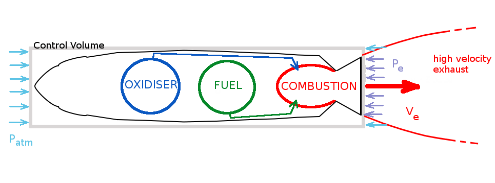
If the rocket is operating within an atmosphere then there will be additional force components due to a pressure imbalance. Drawing a control volume around the system and evaluation the net change in flow momentum and forces with be required in order to more accurately analyse the system.

$$∑F=T+(P_{atm}-P_e)A_e={dm}/{dt}V_e$$
where $P_e$ is the pressure in the exhaust acting on an exhaust area, $A_e$, and $P_{atm}$ is the pressure of the surrounding atmosphere.
Thrust will now be
$$T={dm}/{dt}V_e=(P_{atm}-P_e)A_e$$
It is common practice to include this pressure loss term as a reduction in velocity.
$$T={dm}/{dt}V_e-{dm}/{dt}({(P_{atm}-P_e)A_e}/{{dm}/{dt}})={dm}/{dt}V_e-{dm}/{dt}ΔV={dm}/{dt}V_{equivalent}$$
where $V_{equivalent}$ ($V_{eq}$) is defined as the equivalent exhaust velocity.
In this case the specific impulse is
$$I_{sp}=V_{eq}/g_0$$
Rocket Performance
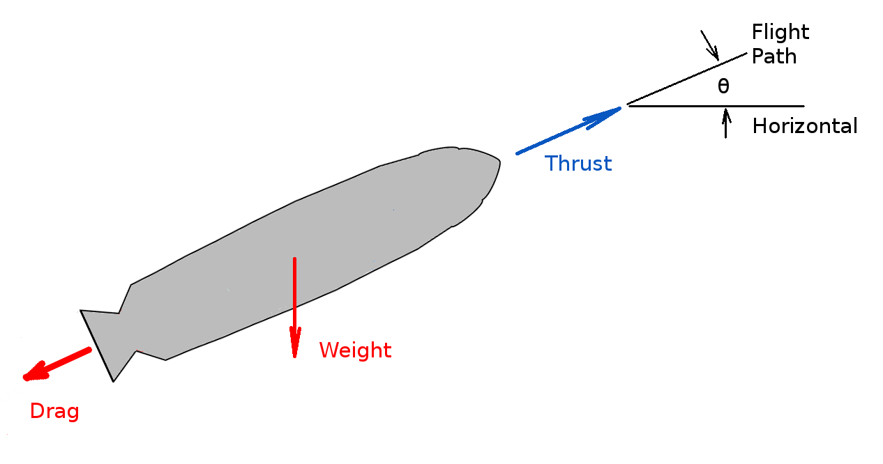
A rocket operating in an atmosphere and under influence of gravity will be subject to the balance of Thrust ($T$) and Drag ($D$) forces and gravitational acceleration. The motion of the rocket can be predicted using a simple force balance.

In the direction of the flight path,
$$∑F=Ma$$
at any instant of time.
where $M$ is the current mass of rocket and $a$ is its current acceleration.
$$Ma=M {dV}/{dt}=T-D-Mg\sin(θ)$$
Note, force components normal to the flight path are ignored in this simple approach but may be significant for long flights.
To find the overall performance, the above equation is integrated over time.
$$dV=∫T/M .dt-∫D/M .dt - ∫ g \sin(θ).dt$$
If velocity, altitude, and flight path angle are changing with time the above equation becomes exceedingly difficult to integrate directly. Numerical integration over small time steps for which properties are assumed constant and then updated for the next step is the usual approach used to solve the full equation.
If the rocket is operating in a vacuum or in orbit such that drag and gravity has negligible component in the flight path direction then the equation can be solved by simple integration.
$$dV=∫T/M .dt$$
Using the previous solution for motor thrust,
$$dV= ∫ {{dm}/{dt}V_e}/M .dt=∫V_e/M {dm}/{dt} .dt=∫V_e/M.dm$$
where $m$ is the change in mass of exhaust gas (fuel) and $M$ is the mass of the rocket.
The change in mass of the rocket ($dM$) will be equal but opposite to the amount of mass going out in the the exhaust ($dm$), $dm = - dM$.
$$dV= -∫V_e/M.dM$$
For a given mass of fuel burnt ($m_b$) the rocket mass will go from an initial value of $M_i$ to a final value of $M_f = M_i – m_b$ and the rocket will be accelerated from an initial velocity $V_i$ to a final velocity $V_f$ , so that $ΔV = V_f - V_i$.
$$∫_{V_i}^{V_f}dV=V_f-V_i=-V_e∫_{M_i}^{M_f}1/M .dM$$
$$ΔV=-V_e(\ln(M_f)-\ln(M_i))=V_e(\ln(M_i)-ln(M_f))=V_e\ln(M_i/M_f)$$
where it is assumed the system is operating at constant exhaust velocity and constant thrust.
If the previous formula for $I_{sp}$ is used to replace exhaust velocity then the result is the ideal rocket performance equation.
$$ΔV=I_{sp}g_o\ln(M_i/M_f)$$